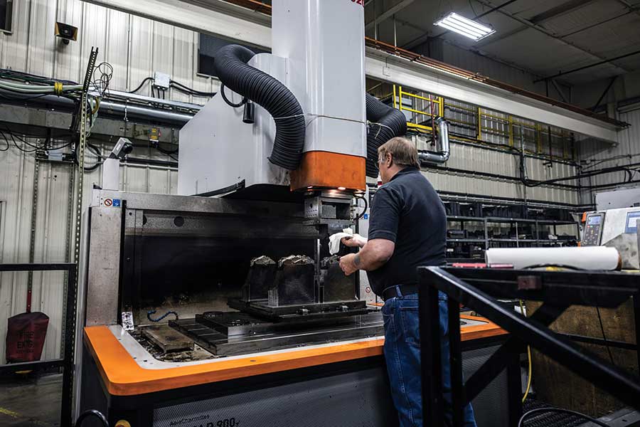
The Tooling Tech Group team provides both low-pressure and high-pressure die cast dies for machines with locking forces that range from 200 to 6,000 tons. Versed in a variety of software, our engineers focus on providing a tooling package that maximizes your process window, facilitates quick die change, simplifies tool maintenance, and ensures interchangeability of die components while our skilled toolmakers meticulously craft the dies using advanced CNC machines and other precision technology. Our purpose is to provide a highly accurate, robust die that results in consistent quality cast components. Learn more about our die cast tooling production dies and design services today.
Die cast mold maintenance is a crucial aspect of ensuring the longevity and efficiency of die casting operations. Tooling Tech Group is equipped to support your dies with regular cleaning, lubrication, and inspection that help prevent wear and tear on the mold components. By addressing any issues promptly and implementing preventive measures, including proper storage and handling practices, we can help to minimize downtime and production disruptions.
Wear and tear on the die can incur issues such as cracks, dents, or worn-out components. Our repair technicians are equipped with specialized tools and techniques to repair these issues effectively. Our state-of-the-art equipment includes a mobile laser welding system for making die repairs to mold cavity surfaces, as well as refurbishment of critical wear surfaces. We also use a mobile laser welding system to make engineering changes to mold cavity surfaces. These systems are highly precise and efficient for correcting and evaluating complex mold features.
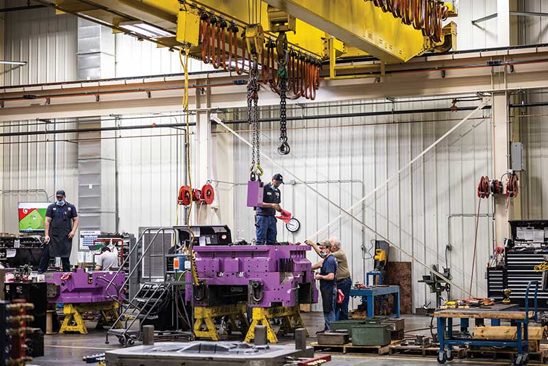
Assembly of the die components is just as important as the overall tool design. Involving inserts, cores, cavities, ejector pins, and cooling channels; all of these components must work together to produce high-quality die cast parts. Our team has years of experience in providing precisely assembled dies that meet your desired specifications.
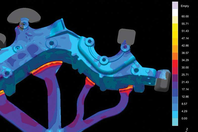
Tooling Tech Group uses flow and thermal simulation to ensure the efficiency and effectiveness of our molds. By inputting parameters such as material properties, part geometry, and injection conditions into the software, we can simulate how molten aluminum will fill the mold cavity and solidify. This information helps to identify potential defects like shrinkage or porosity prior to production, saving time and resources. Additionally, magma simulation allows us to experiment with different design iterations quickly and cost-effectively, ensuring that the final mold meets performance requirements with minimal trial and error.
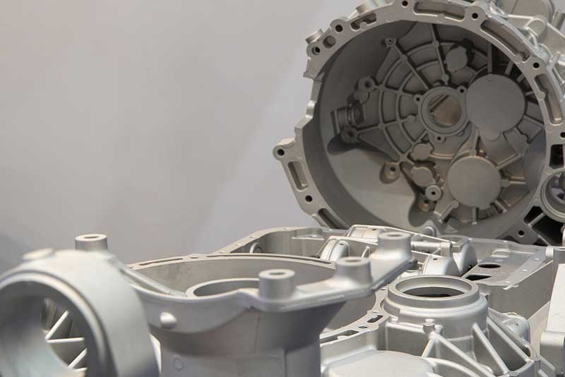
Tooling Tech Group runs die samples when customers require in order to test the functionality, accuracy, and quality of the mold before mass production begins. Through testing and analysis of these samples, adjustments can be made to ensure that the final die cast mold meets all specifications and delivers high-quality results. Additionally, die samples help streamline the manufacturing process by reducing trial-and-error iterations and minimizing costly mistakes during production.
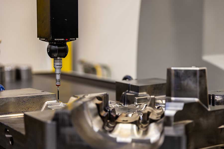
In addition to being a standard service with our die builds, Tooling Tech Group offers tool quality verification as a stand-alone service. To verify the dimensional quality of tooling, we have a portable Romer CMM arm as well as two GOM ATOS Triple Scan high-resolution, 3D optical digitizers for automated measuring and inspection of casting dies. By utilizing these advanced tools, we can accurately measure and analyze every aspect of the mold’s geometry, surface finish, and dimensions. This combination of technologies enables the identification of potential issues, leading to improved efficiency and overall product quality.
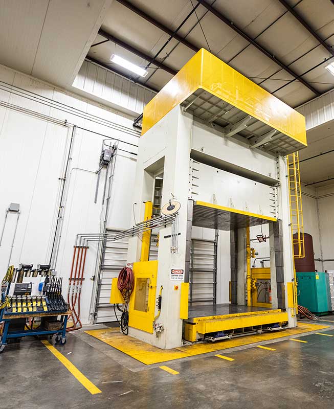
Die spotting is essential to verify the contact surfaces between the moving side and the fixed side of a mold. Using a spotting press to apply pressure and colorant to indicate which surfaces are touching and which are not, we spot every die we build or repair to ensure the aluminum will flow properly through the mold and produce high-quality components.
We have an award-winning history of providing jigs and fixtures that maintain tolerances down to less than a millimeter for our customers. Our engineers are experts in designing optimal solutions to hold, support and locate a workpiece for manufacturing repeatability and accuracy. Incorporating the Six Sigma strategy of Poka-yoke (mistake proofing), our fixtures eliminate the potential of producing incorrect parts along with consideration for ease of assembly, maintenance, interchangeability and end-user ergonomics.
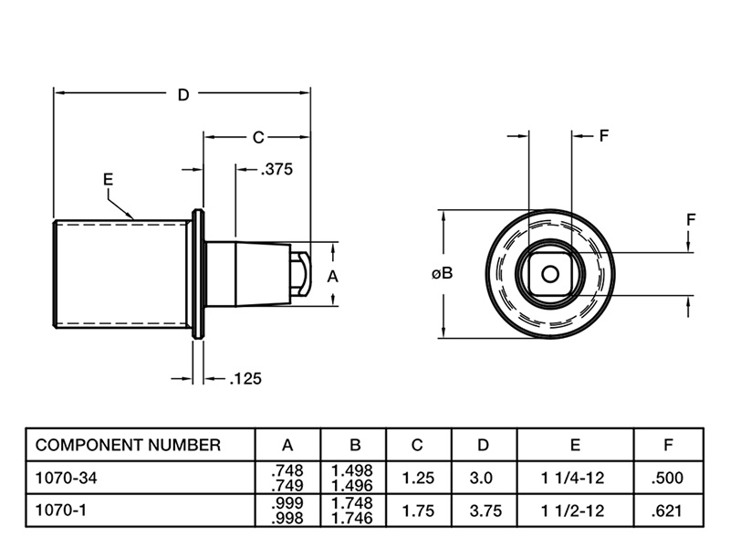
Tooling Tech Group can provide spare components for injection molding tools, which are essential to maintaining production efficiency and minimizing downtime. These spare parts encompass a wide range of items such as the plates, pins, bushings, and blocks that help make up the mold base, as well as mold plates, mold inserts, or other components. Keeping an inventory of spare parts on hand allows you to quickly address any issues that arise during the injection molding process without causing significant delays or disruptions to your operations.
Request a Quote
Proprietary Joining Solutions for Big Boy Toys
In this process, the heavy truck components (about 5-ft x 7-ft in size) are kept in a glue/bond apply station where a robot travels along a shuttle applying the adhesive to the different stations. The operator then manually loads the components in the front half of the cell and six components on the other side of the cell. The side with six components pivots up and is merged with the stationary side with the three components. The cycle then starts where cylinders are engaged to apply the pressure to finalize the bond
Combining Manual and Automated Processes
In this instance our customer asked us to develop a process to bond steel and composite brackets, apply glue and drill holes in a new 2.5 ft x 4 ft component in right-hand and left-hand styles.
In our process, the operator loads the component into the drill where six holes are drilled. The operator then takes the part and puts it into a loading nest where the robot picks up the part and moves it under a stationary dispensing head that applies the glue for the bracket reinforcements. While the glue is being applied, the operator is loading the brackets into the next station. Once these actions are completed, the robot then loads the part into the nest at the manual station and the assembly press closes automatically to complete the bonding process. A mix of two to three operators and one robot results in an efficient cycle time of 3 to 3.5 minutes
Confidential Design to Processing Multiple Part Styles
Our customer provided us the spec sheet outlining the time, temperature and recipe for a foam mix that needed to be applied in order to complete the manufacture of four different composite components.
We developed an automated dual line solution with two 6-axis robots and two shuttles functioning as axis 7 and 8 as the shuttle movements are interlocked with the robots. The operator loads the component on the fixture device and as the shuttle moves, the first robot arm is programmed to apply the foam. This robot then moves out of the way and the second robot moves in and measures the foam bead via a laser measuring system to ensure the right amount was applied. This robot then picks and place the component in the oven. Overall cycle time is 85.9 seconds.
From Four Machines to a Single Line
Our customer needed to produce two versions of a composite automotive part that required the routing of 100 holes and the application of 65 float nuts along with some rivet studs. In addition, they wanted a fully automated solution with +0.25mm tolerance on the holes, zero dust emission and a cycle time of just over three minutes. The customer thought it would take four machines to accomplish this.
Tooling Tech developed a solution that could route all the holes in a single orientation during a continuous process while using a minimum amount of floorspace. The process starts with the operator manually loading the part on a wall fixture where the automated cycle then starts. The part is clamped in place, the part style verified via a sensor, and several holes are drilled. The wall then rotates 180 degrees and a handling robot picks up the part and places it into the route cell where four robots cut about 65 holes. Each robot has a vacuum unit at its head and collects the dust during the routing process.
The handling robot then moves the part to the rivet nut station where two robots apply 66 float nuts, fed to the robots via a pneumatic tube. The nuts go in and are crimped using amperage as an indicator if the nut is properly secured. At the end of this process, all six robots communicate with the material handling robot to determine good or bad part.
Eliminating Human Error
We supplied our customer with a solution for welding two components together, where clinch nuts were already pressed in prior to welding. After welding, manual processes included the insertion of two push pins for a wiring harness operation and the application of a piece of double-sided tape. However, 10 – 15% of the components were being sent to quarantine due to missing parts.
Tooling Tech developed a fixturing station for assembly and a checking station to verify part presence. Once the part is welded, it is manually moved to the assembly station where the pin and tape are put in place. The part is then moved to the checking station where the part is clamped in place, and it goes through an automated checking cycle. Using a variety of sensors, the presence of the tape, clinch nuts and pins are all verified. This has saved the customer about $10,000/week.
In these days of lightweighting, it’s not only performance vehicles that benefit from composite structures. Introduced in 1987, the Jeep Wrangler has become an icon and popular across the world. With the 2018 model re-design, engineers were able to drop 200 pounds from the vehicle by employing aluminum bodywork and composite hardtop panels, with molds supplied by Tooling Tech Group. The frame is also 100 pounds lighter through extensive use of high strength steel.
Originally introduced in 2010, this performance truck shed 500 pounds in its 2017 iteration with a new aluminum body as well as composite hood and front fenders. This 2018 model has the same features, proving that lightweight materials can tough out off-road driving.
From the sleekest and sexiest of vehicles to the biggest boys on the highway, Tooling Tech Group provides molds for many heavy truck manufacturers. When you look at the size of these cabs, you can just imagine the weight reduction being achieved by the usage of composite materials.
This vehicle, commemorating the movie Bullitt starring Steve McQueen, was ‘the thing” at the 2018 Detroit Auto Show. To match the original movie car, this version is light on external badging and painted in the same dark green. However, the original was a steel vehicle and today’s version features composite panels.
Ford’s research into improved efficiency through weight reduction with advanced materials including new metals, alloys and composites began more than 25 years ago. Although the new 2019 Ranger features a high strength steel frame, the company is employing composite truck beds and body panels to help reduce vehicle weight. Other highlights include frame-mounted steel bumpers, an aluminum hood and tailgate, and standard automatic emergency braking and rearview camera.
Tooling Tech Group has long history of providing compression molds for various body panels on the Chevrolet Corvette, most recently providing the molds, bonding, drilling and assembly equipment for the C-7 and C-8 Stingray and Z06. The C6 Z06, introduced in 2006, was recognized for its use of advanced materials including an aluminum frame, magnesium roof structure, engine cradle and other suspension attachment points as well as light-weight, high-strength composite panels for the front fenders, front wheelhouses and rear fenders.